For industrial robots, handling materials is one of the more important applications in their grasping operations. As a kind of working equipment with strong versatility, the successful completion of the operation task of an industrial robot directly depends on the clamping mechanism. Therefore, the clamping mechanism at the end of the robot should be designed according to the actual operation tasks and the requirements of the working environment. This leads to the diversification of the structural forms of the clamping mechanism.
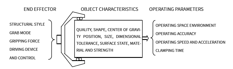
Figure 1 The relationship between the elements, features and parameters of the end effector Most mechanical clamping mechanisms are two-finger claw type, which can be divided into: rotary type and translation type according to the movement mode of fingers; different clamping methods can be divided into inner support According to the structural characteristics, it can be divided into pneumatic type, electric type, hydraulic type and their combined clamping mechanism.
Pneumatic end clamping mechanism
The air source of the pneumatic transmission is more convenient to obtain, the action speed is fast, the working medium is pollution-free, and the fluidity is better than the hydraulic system, the pressure loss is small, and it is suitable for long-distance control. The following are several pneumatic manipulators:
1. Rotary link lever-type clamping mechanism The fingers of this device (such as V-shaped fingers, curved fingers) are fixed on the clamping mechanism by bolts, which is more convenient to replace, so it can significantly expand the application of the clamping mechanism.
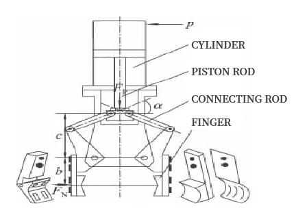
Figure 2 Rotary link lever type clamping mechanism structure 2. Straight rod type double cylinder translation clamping mechanism The finger end of this clamping mechanism is usually installed on a straight rod equipped with a finger end mounting seat. When the two rod cavities of the double-acting cylinder are used, the piston will gradually move to the middle until the workpiece is clamped.
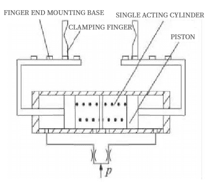
Figure 3 Structural diagram of the straight-rod double-cylinder translation clamping mechanism 3. The connecting rod cross-type double-cylinder translation clamping mechanism is generally composed of a single-acting double cylinder and a cross-type finger. After the gas enters the middle cavity of the cylinder, it will push the two pistons to move to both sides, thereby driving the connecting rod to move, and the crossed finger ends will firmly fix the workpiece; if no air enters the middle cavity, the piston will be under the action of the spring thrust Reset, the fixed workpiece will be released.
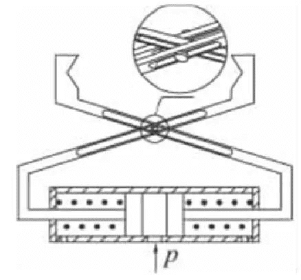
Figure 4. Structure of the cross-type double-cylinder translation clamping mechanism Thin-walled workpieces with inner holes. After the clamping mechanism holds the workpiece, in order to ensure that it can be positioned smoothly with the inner hole, usually 3 fingers are installed.
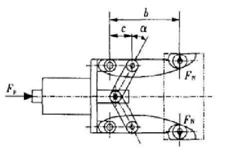
Figure 5 Structural diagram of the lever-type clamping mechanism of the inner support rod 5. The booster mechanism driven by the fixed rodless piston cylinder Under the action of spring force, the reversing is realized by the two-position three-way solenoid valve.
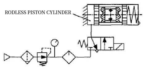
Figure 6 Pneumatic system of fixed rodless piston cylinder A transition slider is installed at the radial position of the piston of the rodless piston cylinder, and two hinge rods are symmetrically hinged at both ends of the slider. If an external force acts on the piston, the piston will It will move left and right, thereby pushing the slider to move up and down. When the system is clamped, the hinge point B will make a circular motion around the point A, and the up and down movement of the slider can add a degree of freedom, and the oscillation of the point C replaces the oscillation of the entire cylinder block.
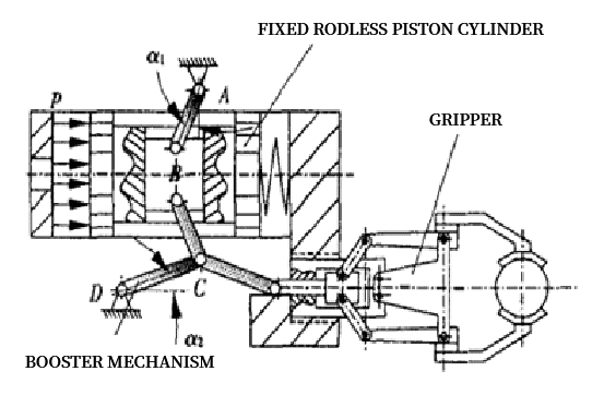
Figure 7 The force-enhancing mechanism driven by the fixed rodless piston cylinder
When the directional control valve of the compressed air is in the left working state as shown in the figure, the left cavity of the pneumatic cylinder, that is, the rodless cavity, enters the compressed air, and the piston will move to the right under the action of the air pressure, so that the pressure angle α of the hinge rod gradually decreases. Small, the air pressure is amplified by the angle effect, and then the force is transmitted to the lever of the constant boosting force lever mechanism, the force will be amplified again, and become the force F for clamping the workpiece. When the directional control valve is in the working state of the right position, the rod cavity in the right cavity of the pneumatic cylinder enters the compressed air, pushes the piston to move to the left, and the clamping mechanism releases the workpiece.
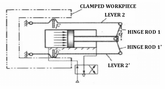
Figure 8. The inner clamping pneumatic manipulator of the hinge rod and 2 lever series booster mechanism
Two Air suction end clamping mechanism
The air suction end clamping mechanism uses the suction force formed by the negative pressure in the suction cup to move the object. It is mainly used to grab glass, paper, steel and other objects with large shape, moderate thickness and poor rigidity. According to the negative pressure generation methods, it can be divided into the following types: 1. Squeeze suction cup The air in the suction cup is squeezed out by the downward pressing force, so that negative pressure is generated inside the suction cup, and suction force is formed to suck the object. It is used to grab workpieces with small shape, thin thickness and light weight.
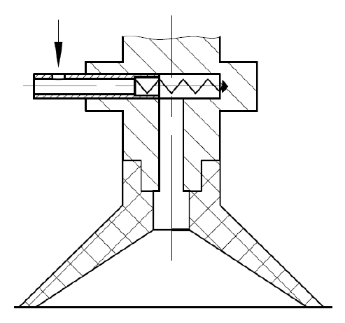
Figure 9 Structural diagram of the squeeze suction cup 2. The air flow negative pressure suction cup control valve sprays the compressed air from the air pump from the nozzle, and the flow of the compressed air will generate a high-speed jet, which will take away the air in the suction cup, so that the suction cup is in the suction cup. Negative pressure is generated inside, and the suction formed by the negative pressure can suck the workpiece.
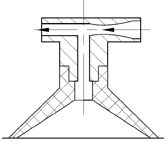
Figure 10 Structural diagram of airflow negative pressure suction cup
3. The vacuum pump exhaust suction cup uses an electromagnetic control valve to connect the vacuum pump with the suction cup. When the air is pumped, the air in the suction cup cavity is evacuated, forming a negative pressure and sucking the object. Conversely, when the control valve connects the suction cup to the atmosphere, the suction cup loses suction and releases the workpiece.
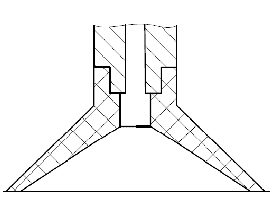
Figure 11 Structural diagram of vacuum pump exhaust suction cup
Three hydraulic end clamping mechanism
1. Normally closed clamping mechanism: The drilling tool is fixed by the strong pre-tightening force of the spring and released hydraulically. When the clamping mechanism does not perform the grabbing task, it is in the state of clamping the drilling tool. Its basic structure is that a group of pre-compressed springs act on a force-increasing mechanism such as a ramp or a lever, so that the slip seat moves axially, drives the slip to move radially, and clamps the drilling tool; high-pressure oil enters the slip seat and The hydraulic cylinder formed by the casing further compresses the spring, causing the slip seat and the slip to move in the opposite direction, releasing the drilling tool. 2. Normally open clamping mechanism: It usually adopts spring release and hydraulic clamping, and is in a released state when the grasping task is not performed. The clamping mechanism relies on the thrust of the hydraulic cylinder to generate the clamping force, and the reduction of the oil pressure will lead to the reduction of the clamping force. Usually, a hydraulic lock with reliable performance is installed on the oil circuit to maintain the oil pressure. 3. Hydraulic tightening clamping mechanism: Both loosening and clamping are realized by hydraulic pressure. If the oil inlets of the hydraulic cylinders on both sides are connected to high-pressure oil, the slips will close to the center with the movement of the piston, clamp the drilling tool, and change the The high pressure oil inlet, the slips are away from the center, and the drilling tool is released.
4. Compound hydraulic clamping mechanism: This device has a main hydraulic cylinder and an auxiliary hydraulic cylinder, and a set of disc springs is connected to the auxiliary hydraulic cylinder side. When the high-pressure oil enters the main hydraulic cylinder, it pushes the main hydraulic cylinder block to move, and passes through the top column. The force is transmitted to the slip seat on the side of the auxiliary hydraulic cylinder, the disc spring is further compressed, and the slip seat moves; at the same time, the slip seat on the main hydraulic cylinder side moves under the action of the spring force, releasing the drilling tool.
Four magnetic end clamping mechanism
Divided into electromagnetic suction cups and permanent suction cups.
The electromagnetic chuck is to attract and release ferromagnetic objects by turning on and off the current in the coil, generating and eliminating magnetic force. The permanent magnet suction cup uses the magnetic force of permanent magnet steel to attract ferromagnetic objects. It changes the magnetic field line circuit in the suction cup by moving the magnetic isolation object, so as to achieve the purpose of attracting and releasing objects. But it is also a sucker, and the suction force of the permanent sucker is not as large as that of the electromagnetic sucker.
Post time: May-31-2022