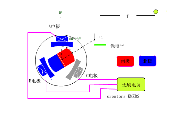
1. FOC
Field-oriented control, also known as vector control, is a method to control the output of the motor by adjusting the output frequency of the inverter, the magnitude and angle of the output voltage.
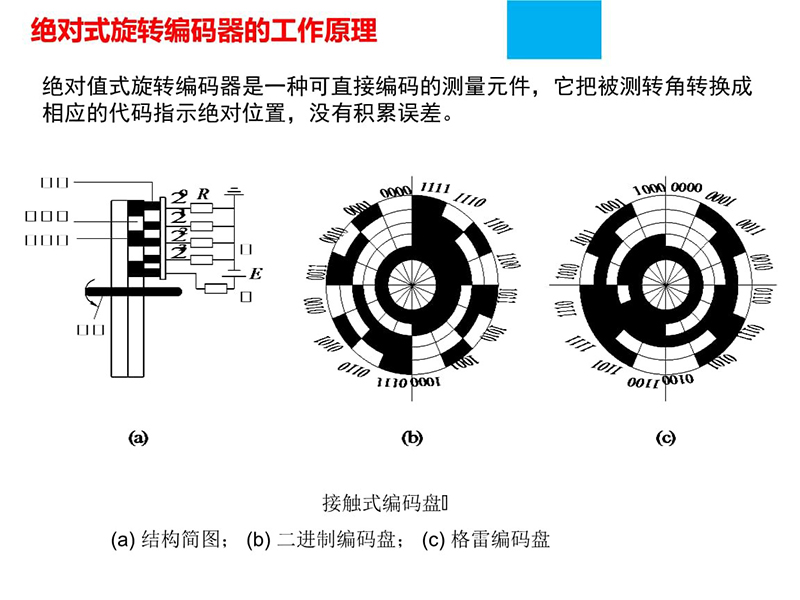
2. Encoder zero alignment
Align the servo motor encoder phase with the rotor pole phase zero. The position detected by the magnetic encoder is a mechanical angle, according to such as
The following formula converts to electrical degrees.
Electrical angle = mechanical angle × number of pole pairs
RG/EPG series products leave the factory for an encoder zero calibration, and store the information in EEPROM.
Zero operation steps:
1) Write the encoder zeroing instruction (0×01) to the encoder register (0x03FB)
2) Enable the electric gripper and perform encoder zeroing.
3. Enable/Activate
After the electric gripper moves to the structural limit position in the opening direction, it moves to the structural limit position in the closing direction.
Through the enabling operation, the electric gripper completes the stroke search function. During the enabling process, it is necessary to ensure that there are no obstacles blocking the finger movement.
Otherwise, it will lead to a deviation in stroke search and affect the normal use of electric grippers.
Notice:
1) The enable operation only needs to be performed once. After the enable is completed, it needs to be “disabled” before it can be re-enabled.
2) If the electric gripper is not enabled and the control command is sent directly, the electric gripper will perform the enabling operation instead of the sent control command.
3) If there is a workpiece in the finger during the enabling process, the clamping force will be insufficient when performing the clamping operation, and there will be errors in the clamping feedback.
4. Serial port/parallel port:
Serial port, serial communication interface, that is, COM port. Data bit serial transmission, common RS485, RS232, USB, etc.
Parallel port, parallel communication interface, multiple data bits are transmitted in parallel, the data transmission speed is fast, but the transmission line length is limited, long
Increased susceptibility to interference. Common DB9, DB25 connectors.
5. RS485:
for electrical standards
The balanced transmission method is adopted, and a terminal resistor needs to be connected to the transmission line.
Two-wire differential signal
Logic “1″ is based on the voltage difference between the two lines + (2~6)V
Logic “0″ is represented by the voltage difference between the two lines – (2~6)V
The maximum communication distance is about 1200m, the maximum transmission rate is 10Mb/s, and the transmission rate is inversely proportional to the transmission distance.
The RS-485 bus generally supports a maximum of 32 nodes.
Twisted-pair cables are used to reduce common-mode interference of signals.
 6. Modbus:
Modbus is a serial communication protocol and a master/slave architecture protocol. In the communication network, there is a
The master node is responsible for actively scheduling the communication process; and allows multiple (about 240) slave nodes, each slave
Devices have a unique address.
RG/EPG series electric gripper
Slave address range: 1~247 (one question and one answer)
Support broadcast communication: 0×00 (only execute operation, no reply)
Modbus-RTU/ASCII:
Both support RS-485 bus, among which Modbus-RTU adopts binary and compact data structure, and the communication efficiency is relatively high.
High; while Modbus-ASCII uses ASCII code transmission, and uses special characters as its byte start and end marks,
The transmission efficiency is low.
Modbus-TCP:
The Modbus TCP protocol adds an MBAP packet header to the RTU protocol and removes the CRC check code.
The Modbus protocol we use is Modbus-RTU.
Post time: Dec-21-2022